ECAD (Electronic CAD) Diagram Family
Electronic circuit diagrams with 18 component nodes covering passive components, semiconductors, ICs, power, and tracing.
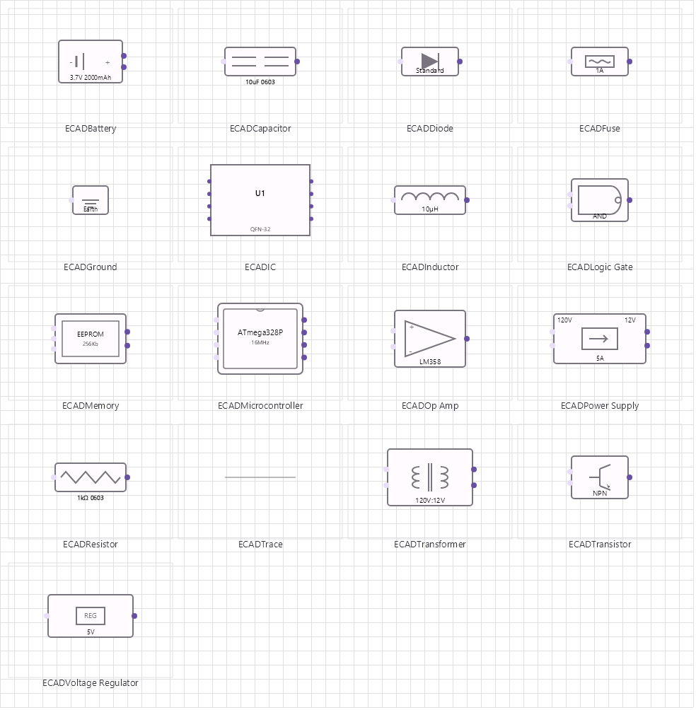
Overview
Base Control: ECADControl : MaterialControl
Namespace: Beep.Skia.ECAD
The ECADControl is the root control for this diagram family. It inherits MaterialControl and provides shared port management, styling, and template methods for all nodes in the family.
This family contains 17 node types.
Node Types
| Node Class | Shape | Description |
|---|---|---|
ECADResistorNode | Zigzag line | Resistor with value and tolerance. |
ECADCapacitorNode | Parallel plates | Capacitor (polarized or non-polarized). |
ECADDiodeNode | Triangle with bar | Diode including LED, Zener, Schottky variants. |
ECADFuseNode | Wire with break | Fuse/circuit breaker. |
ECADICNode | Rectangle with pin grid | Integrated circuit with configurable pin count. |
ECADInductorNode | Coil loops | Inductor/coil with inductance value. |
ECADOpAmpNode | Triangle with +/- inputs | Operational amplifier with inverting/non-inverting inputs. |
ECADTransistorNode | Circle with 3 legs | BJT (NPN/PNP) with collector, base, emitter. |
ECADGroundNode | Ground symbol | Ground/reference point. |
ECADBatteryNode | Long/short line pair | DC power source. |
ECADPowerSupplyNode | Circle with +/- | Power supply unit with voltage/current output. |
ECADVoltageRegulatorNode | Rectangle with Vout | Linear/switching voltage regulator. |
ECADTransformerNode | Two coils | Transformer with primary/secondary windings. |
ECADLogicGateNode | AND/OR/NOT gate symbol | Logic gate (AND, OR, NOT, NAND, NOR, XOR). |
ECADMicrocontrollerNode | Rectangle with pins | Microcontroller/MCU with GPIO, ADC, UART, I2C. |
ECADMemoryNode | Rectangle with address/data | Memory chip (RAM, ROM, EEPROM, Flash). |
ECADTraceNode | Line with width | PCB trace/routing line with configurable width. |
ECADResistorNode
Resistor with value and tolerance.
| Shape | Zigzag line |
|---|---|
| Input Ports | 1 |
| Output Ports | 1 |
ECADCapacitorNode
Capacitor (polarized or non-polarized).
| Shape | Parallel plates |
|---|---|
| Input Ports | 1 |
| Output Ports | 1 |
ECADDiodeNode
Diode including LED, Zener, Schottky variants.
| Shape | Triangle with bar |
|---|---|
| Input Ports | 1 |
| Output Ports | 1 |
ECADFuseNode
Fuse/circuit breaker.
| Shape | Wire with break |
|---|---|
| Input Ports | 1 |
| Output Ports | 1 |
ECADICNode
Integrated circuit with configurable pin count.
| Shape | Rectangle with pin grid |
|---|---|
| Input Ports | 4+ (left) |
| Output Ports | 4+ (right) |
ECADInductorNode
Inductor/coil with inductance value.
| Shape | Coil loops |
|---|---|
| Input Ports | 1 |
| Output Ports | 1 |
ECADOpAmpNode
Operational amplifier with inverting/non-inverting inputs.
| Shape | Triangle with +/- inputs |
|---|---|
| Input Ports | 2 |
| Output Ports | 1 |
ECADTransistorNode
BJT (NPN/PNP) with collector, base, emitter.
| Shape | Circle with 3 legs |
|---|---|
| Input Ports | 1 |
| Output Ports | 1 |
ECADGroundNode
Ground/reference point.
| Shape | Ground symbol |
|---|---|
| Input Ports | 1 |
| Output Ports | 0 |
ECADBatteryNode
DC power source.
| Shape | Long/short line pair |
|---|---|
| Input Ports | 0 |
| Output Ports | 1 |
ECADPowerSupplyNode
Power supply unit with voltage/current output.
| Shape | Circle with +/- |
|---|---|
| Input Ports | 0 |
| Output Ports | 1+ |
ECADVoltageRegulatorNode
Linear/switching voltage regulator.
| Shape | Rectangle with Vout |
|---|---|
| Input Ports | 1 |
| Output Ports | 1 |
ECADTransformerNode
Transformer with primary/secondary windings.
| Shape | Two coils |
|---|---|
| Input Ports | 2 |
| Output Ports | 2 |
ECADLogicGateNode
Logic gate (AND, OR, NOT, NAND, NOR, XOR).
| Shape | AND/OR/NOT gate symbol |
|---|---|
| Input Ports | 2+ |
| Output Ports | 1 |
ECADMicrocontrollerNode
Microcontroller/MCU with GPIO, ADC, UART, I2C.
| Shape | Rectangle with pins |
|---|---|
| Input Ports | 8+ |
| Output Ports | 8+ |
ECADMemoryNode
Memory chip (RAM, ROM, EEPROM, Flash).
| Shape | Rectangle with address/data |
|---|---|
| Input Ports | 4+ |
| Output Ports | 4+ |
ECADTraceNode
PCB trace/routing line with configurable width.
| Shape | Line with width |
|---|---|
| Input Ports | 0 |
| Output Ports | 0 |
Connection Points
Every node in this family exposes connection points (ports) for linking to other nodes. Port positions are computed lazily by LayoutPorts(), which runs when MarkPortsDirty() flags the layout as stale after a move or resize.
| Node Class | Input Ports | Output Ports | Extra |
|---|---|---|---|
ECADResistorNode | 1 | 1 | — |
ECADCapacitorNode | 1 | 1 | — |
ECADDiodeNode | 1 | 1 | — |
ECADFuseNode | 1 | 1 | — |
ECADICNode | 4+ (left) | 4+ (right) | — |
ECADInductorNode | 1 | 1 | — |
ECADOpAmpNode | 2 | 1 | — |
ECADTransistorNode | 1 | 1 | — |
ECADGroundNode | 1 | 0 | — |
ECADBatteryNode | 0 | 1 | — |
ECADPowerSupplyNode | 0 | 1+ | — |
ECADVoltageRegulatorNode | 1 | 1 | — |
ECADTransformerNode | 2 | 2 | — |
ECADLogicGateNode | 2+ | 1 | — |
ECADMicrocontrollerNode | 8+ | 8+ | — |
ECADMemoryNode | 4+ | 4+ | — |
ECADTraceNode | 0 | 0 | — |
Connection Conventions
When building diagrams with this family, follow these conventions:
- Components follow IEEE/ANSI standard symbols
- IC pins are configurable via NodeProperties
- Ground and power are global reference nodes
- Traces connect component ports
Usage Example
Complete example showing creation, node placement, and connection:
C# Example
var ecad = new ECADControl
{
    X = 50, Y = 50,
    Width = 700, Height = 500
};
drawingManager.AddComponent(ecad);

var bat = new ECADBatteryNode { X = 100, Y = 200, Voltage = "9V" };
var res = new ECADResistorNode { X = 250, Y = 150, Resistance = "1kΩ" };
var led = new ECADDiodeNode { X = 400, Y = 150, ForwardVoltage = "2.1V" };
var gnd = new ECADGroundNode { X = 400, Y = 300 };

drawingManager.AddComponent(bat);
drawingManager.AddComponent(res);
drawingManager.AddComponent(led);
drawingManager.AddComponent(gnd);

drawingManager.ConnectComponents(bat.OutPoints[0], res.InPoints[0]);
drawingManager.ConnectComponents(res.OutPoints[0], led.InPoints[0]);
drawingManager.ConnectComponents(led.OutPoints[0], gnd.InPoints[0]);
Electrical Rules Check
ElectricalRulesChecker validates the electrical consistency of the diagram: floating inputs, conflicting drivers, missing power or ground, and pin-type mismatches. Violations are data, not exceptions:
| Member | Type | Description |
|---|---|---|
RunChecks(components, lines) | void | Runs every rule and fills Violations. |
Violations | List<ElectricalRuleViolation> | One entry per problem found. |
ElectricalRuleViolation.Message | string | Human-readable description. |
ElectricalRuleViolation.Severity | ElectricalViolationSeverity | Warning or error. |
ElectricalRuleViolation.Category | string | Rule family that produced the violation. |
ElectricalRuleViolation.FixSuggestion | string | Suggested remedy, when known. |
ElectricalRuleViolation.Component / Port / Line | model refs | What the violation is attached to, for selection and highlighting. |
var checker = new ElectricalRulesChecker();
checker.RunChecks(drawingManager.GetComponents().ToList(), drawingManager.GetLines());

int errors = checker.Violations.Count(v => v.Severity == ElectricalViolationSeverity.Error);
foreach (var violation in checker.Violations)
    Console.WriteLine($"[{violation.Severity}] {violation.Category}: {violation.Message}");