State Machine Diagram Family
State machine diagrams with initial, state, and final nodes for modeling system behavior and state transitions.
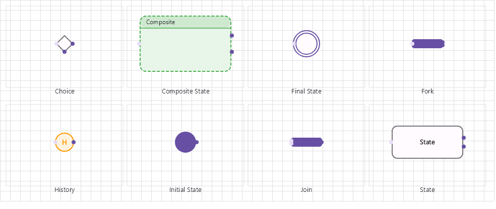
Overview
Base Control: StateMachineControl : MaterialControl
Namespace: Beep.Skia.StateMachine
The StateMachineControl is the root control for this diagram family. It inherits MaterialControl and provides shared port management, styling, and template methods for all nodes in the family.
This family contains 3 node types.
Node Types
| Node Class | Shape | Description |
|---|---|---|
InitialStateNode | Filled circle (black) | Initial pseudo-state. Where the state machine begins. |
StateNode | Rounded rectangle | Named state with optional entry/exit/do actions and internal transitions. |
FinalStateNode | Circle with inner filled circle (bullseye) | Final termination state. |
InitialStateNode
Initial pseudo-state. Where the state machine begins.
| Shape | Filled circle (black) |
|---|---|
| Input Ports | 0 |
| Output Ports | 1 |
StateNode
Named state with optional entry/exit/do actions and internal transitions.
| Shape | Rounded rectangle |
|---|---|
| Input Ports | 1+ |
| Output Ports | 1+ |
FinalStateNode
Final termination state.
| Shape | Circle with inner filled circle (bullseye) |
|---|---|
| Input Ports | 1+ |
| Output Ports | 0 |
Connection Points
Every node in this family exposes connection points (ports) for linking to other nodes. Port positions are computed lazily by LayoutPorts(), which runs when MarkPortsDirty() flags the layout as stale after a move or resize.
| Node Class | Input Ports | Output Ports | Extra |
|---|---|---|---|
InitialStateNode | 0 | 1 | — |
StateNode | 1+ | 1+ | — |
FinalStateNode | 1+ | 0 | — |
Connection Conventions
When building diagrams with this family, follow these conventions:
- Initial state has no inputs, one output transition
- State transitions are labeled with trigger[guard]/action
- Final state has inputs but no outputs
- States may contain do/entry/exit activity compartments
Usage Example
Complete example showing creation, node placement, and connection:
C# Example
var sm = new StateMachineControl
{
    X = 50, Y = 50,
    Width = 600, Height = 400
};
drawingManager.AddComponent(sm);

var init = new InitialStateNode { X = 100, Y = 200 };
var idle = new StateNode { X = 250, Y = 200, StateName = "Idle" };
var active = new StateNode { X = 400, Y = 100, StateName = "Active" };
var final = new FinalStateNode { X = 400, Y = 300 };

drawingManager.AddComponent(init);
drawingManager.AddComponent(idle);
drawingManager.AddComponent(active);
drawingManager.AddComponent(final);

drawingManager.ConnectComponents(init.OutPoints[0], idle.InPoints[0]);
drawingManager.ConnectComponents(idle.OutPoints[0], active.InPoints[0]);
drawingManager.ConnectComponents(active.OutPoints[0], final.InPoints[0]);
States and Transitions
A state machine is a StateNode graph where the transition semantics live on the connection lines. States carry their behaviour; lines carry the trigger, guard and action:
| Member | On | Description |
|---|---|---|
Title | StateNode | State name shown in the shape. |
EntryAction | StateNode | Behaviour executed when the state is entered. |
ExitAction | StateNode | Behaviour executed when the state is left. |
DoActivity | StateNode | Activity performed while in the state. |
TriggerEvent | ConnectionLine | Event that fires the transition. |
GuardCondition | ConnectionLine | Predicate that must hold (for example [balance >= amount]). |
TransitionAction | ConnectionLine | Behaviour executed during the transition. |
The three line properties also appear on the line's labels, so a transition can be read directly on the canvas: trigger [guard] / action. They are persisted with the diagram and validated by the diagram validator when transitions are unreachable.
drawingManager.ConnectComponents(idle, processing);

var transition = drawingManager.GetLines().Last();
transition.TriggerEvent = "order.received";
transition.GuardCondition = "order.items > 0";
transition.TransitionAction = "reserveInventory()";
transition.Label1 = "order.received [items > 0] / reserveInventory()";